
|

|
Video killed the radio star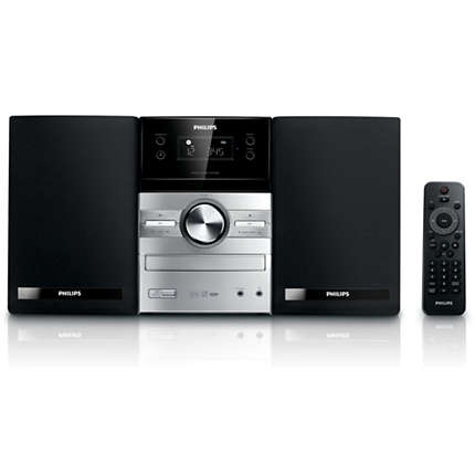
-Snoop Dogg
Home automation is cool. But things get fucky when you DIY. Look at this high end marvel of technology, the audiophiles most wanted: The glorious Philips MCM205 Micro System.
How does one automate this? With FHEM and an IR Diode you say? Yes but no. This lousy noisemaker uses some funky IR voodoo on a nonstandard wavelength. So you can only control this thing in the dark. (or my setup is too ghetto - anyway it didn't work reliably)
Internet of Thongs™ to the rescue!
IoT is the future, people say. Allrighty then we can totally WLANify this thing, and add another insecure device to our network. How hard can it be?
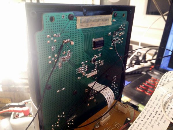
Let's look inside:

Interesting: the AM/FM Radio seems to be a separate module:

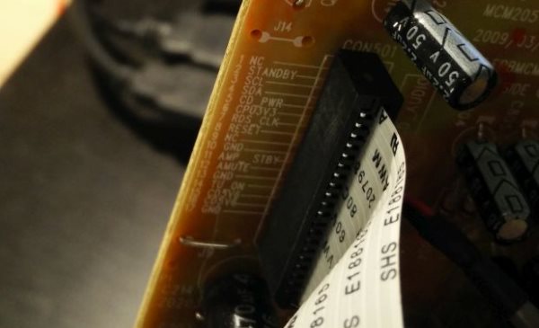
The engineers were nice enough to label the pins
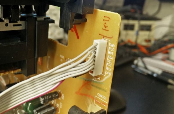
Wohey, hold your horses! It seems that thing only gets power, and outputs analog audio via RCH and LCH. And it's controlled via I²C (SCL/SDA).
Let's get the old Osmelloscope out and check
(WELCOME TO THE FUTURE: The Osmelloscope can even tell me the data! Noice!)

Ok, what now? I have no clue what's happening here. Oh well, Bus Pirate to the rescue!
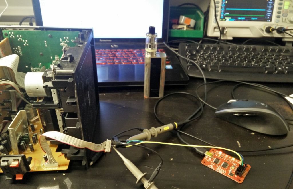
(vapenation represent)
So, every time the radio switches modes, it seems to write some data somewhere, and on returning to FM mode, it reads data. Even with the FM Module not connected. What the who? Is there an EEPROM somewhere? Lets look at the data:
Change mode from FM to something else:
[0xA0 0x82 0x28 0x8C]
On power on and switching to FM:
[0xA0 0x82]
[0xA1 0x28 0x8C]
The set frequency was 103,8. 288C in decimal is 10380. Seems the radio has an EEPROM somewhere on the main PCB, and stores the current tuning to it when switching modes, and reading it when the tuner is activated. After looking at page 3034234524563 on Google i found a schematic! I thought they don't make em anymore. Here it is. Fantasticulo!

GOTCHA!
Allrighty, 24C02 is a 2K I²C EEPROM. Dumping it reveals:
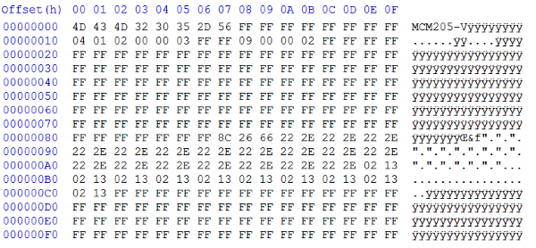
nothing. Ok fuck this noise, i'll just look at this later. But we now know the Tuning frequency of the current setting is stored at 0x82 as a two-byte value. Also, the dump seems to have been successful (look at the first few bytes)
Controlling Stuff
That's all fine and dandy monsieur Wummi, but how do we even control this thing now? Let me tell you! With the power of ESP8266! It's a cheap microcontroller with built-in WiFi. They even make cheap and easy dev-boards called the NodeMcu, sporting a sexy ESP8266, USB-UART and voltage regulator. And pins that are not so small that you will mos-def fuck em up trying to solder them. And they are cheap! 4,50€ on Amazon with free shipping! Don't even bother with the chip-only thing, just whack the whole devboard into whatever project you might have, and be able to easily upgrade the firmware via usb. That's what i'm gonna do to this radio anyhow.
Allrighty then, this radio has a pushbutton on the front to turn it on and off. Seems to have a pull-up resistor. So let's just solder a wire to it and pull it low with the ESP. Easy peasy.
Ok cool, this worked out fine. But wait! The radio has lots of buttons. But only 3 Wires are connected to the main pcb? Dafuq? Something tricky is going on. Wouldn't it be nice to also only use 3 pins from the ESP and control ALL THE BUTTONS? How does this even work you say? The answer: It's connected to ADC Pins of the radio µC. The buttons have different resistors and are wired in series:

OK, the µC does different things depending on the voltage on those 3 wires. I tried PWMing this, but no cigar.
At this point we have 2 options: Solder a wire to every button and connect it to the ESP, or find a different solution. Wiring all the buttons is not only annoying, the ESP doesn't even have enough IOs for that. Also there is no way to emulate the volume encoder without disconnecting it. So what do?
Remote via IR (wait what)
Remember i said the IR on this thing is wack? Because it is. But for photon-related reasons. Why not communicate directly with the Chip via the IR protocol! That's gonna show em!
So let's solder another wire, and think about the consequences later:
Ok now, but i have no idea how IR protocols work, or what kind of protocol this thing even speaks. There is a shitload of them, and some modified versions on top of that. Also i'm not gonna implement it anyway for a few buttons on a funky old radio. Let's not bother with that and switch to easy mode.
IR hax0ring the easy way
The IR receiver in the radio already does all the demodulation and puts out a noice digital signal, let's look at it:

(don't get all upset, my ground connection is bad, mhkay? haters gonna hate)
Okay then, we just gotta pull that line down like this and it should work. How? NodeMcu has us covered: gpio.serout() does exactly this. Let's look at the thing again:

Short pulse length is about 1ms, long pulse about double. So we can encode our commands with an array of short and long pulses. But i'm not gonna look at waveforms and note the modulation down on some notepad like a neanderthal. Let's be lazy and use a cool feature of most DSOs: Test mode or Mask mode or whatever its called. It lets us record a waveform basically:

So all we have to do now is wing the hammer at the NodeMcu, not worrying about timings, interrupts or whatever. Just hit it like beckham until the waveform fits. Was nicht passt, wird passend gemacht.
Attention, luascript incoming:
k = 870
l = 1750
ssw = 0
pin = 2
gpio.mode(pin,gpio.OUTPUT)
gpio.serout(pin,gpio.HIGH,{k,k,k,k,k,k,k,l,k,k,k,k,k,k,k,k,l,l,k,k,k,k,l,k},1)
The constants are not exactly 1000 and 2000 because.... the NodeMcu does hokuspokus. I just adjust it until it looks right on the DSO:

Lets just add k and l as we go along....

Meh, good enough. The timing is a little off, but it works. Doneski!
Intermisson: I also tried to hax0r the LCD for sexy and smooth messages. I failed. If you are interested look here. If not, read on:
So this radio only has one button for on/off. Wouldn't be nice to know if its on or off, so FHEM knows whats going on? Nice as the Philips engineers were they provided us with another nice pin:
Aww yiss! Pin 2 goes high when the radio is on, and low when in standby. Gotta love those PCB silkscreens. So lets solder another cable directly to the ESP.
All the things in the radio are pulled up by default, and the ESP has floating 3v3 pins, so all is well.
Remember the EEPROM?
Well we know the eeprom stores (among other things) the set frequency. So can we hongobongo a frequency to the ESP and it will switch the radio for us? You bet yo mamas ass.
It werks like: Switch to another mode via IR command, overwrite the frequency in EEPORM and switch back to FM. The radiocontroller will read the frequency and set it on the tuner module, and display it on the LCD. As there seems to be silence on the I²C bus in AM mode, we can take the bus over. Ah and the NodeMcu comes with an I²C library. All is well!
Lets build crappy software
How do we build an interface that is easy to implement on whatever is going to control the radio? HTTP seems good. So:
srv=net.createServer(net.TCP)
srv:listen(80,function(conn)
conn:on("receive",function(conn,payload)
-- print(payload)
tgtfile = string.sub(payload,string.find(payload,"GET /")
+5,string.find(payload,"HTTP/")-2)
A few lua lines and we have a webserver thats good enough, and executes a function based on whatever comes after the / in the get request. The rest is left as exercise for the reader.
With all this we now have:
a GET API that allows us to
- Push all the buttons
- Set an arbitrary FM frequency
- Check if the radio is on or off
- Profit
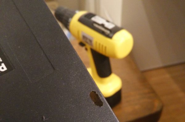
Put it together
Well thats all nice and swaggy, remember when i told you to just whack the whole board in to save you from angryness? Thats what i did. And to be able to funk around with the software without disassembling the whole thing, lets just mount the NodeMcu like a professional and make a noice usb hole:
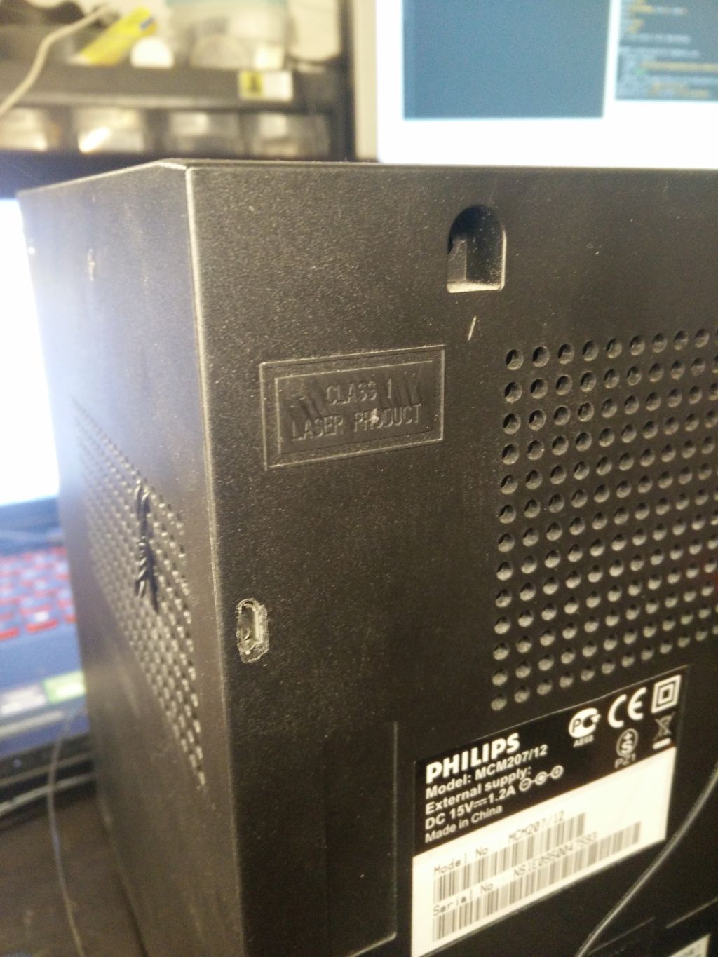
CLASS 1 USB PRODUCT
But in the end, it all worked out #swag